Battery Management System
A system that redistributes energy from the stronger cells to the weaker cells in a battery pack in order to maximize the capacity available to the load at its operating voltage.
Problem
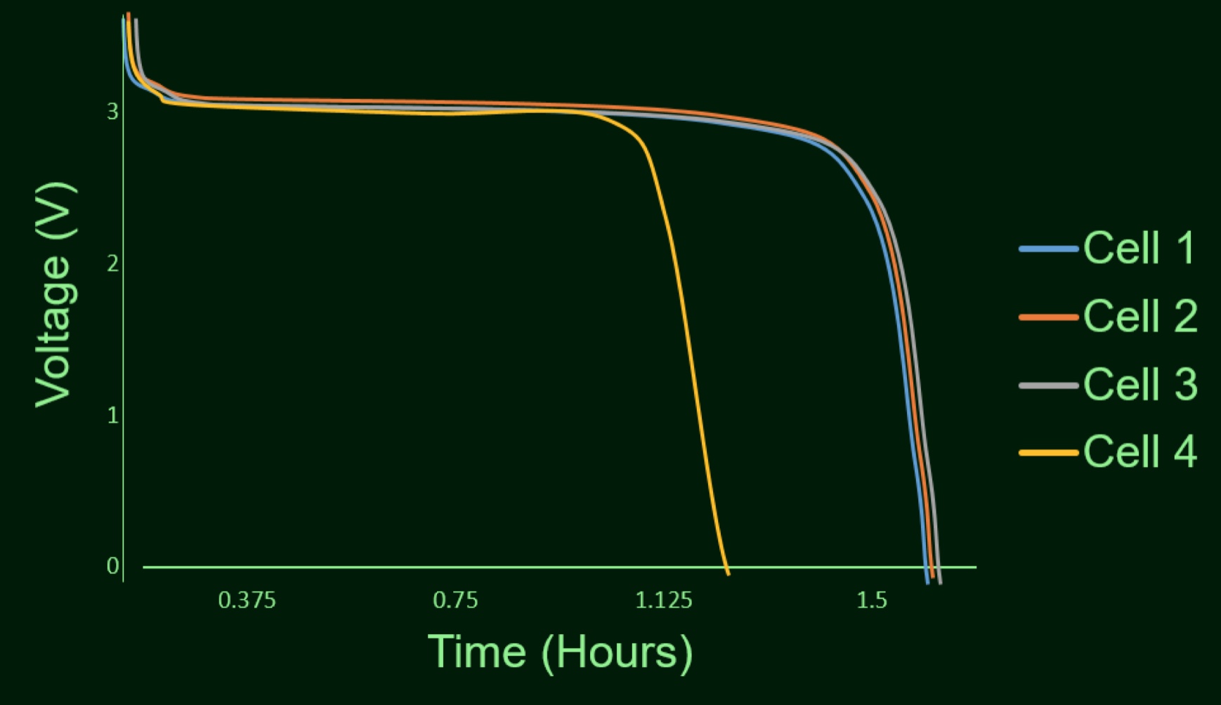 Over time, in a battery pack, individual cells begin to degrade. This leads to the battery pack voltage decreasing prematurely. Even though there is still energy stored in the other "stonger" battery cells, the weak one acts as a bottleneck. The picture to the left shows the dissipation curves of 4 different lithium iron phosphate battery cells. Cell number 4 is damaged and the voltage drops off sooner than the others. This means the system will only last until this cell loses its charge, significantly reducing the available capacity of the battery pack. The weak cell acts as a “weak point” and reduces the ability of the pack to hold a charge. Once the voltage of the weak cell drops, the entire pack voltage will drop below the load's minimum operating voltage. In most applications, this causes the load to stop operating correctly.
How it works
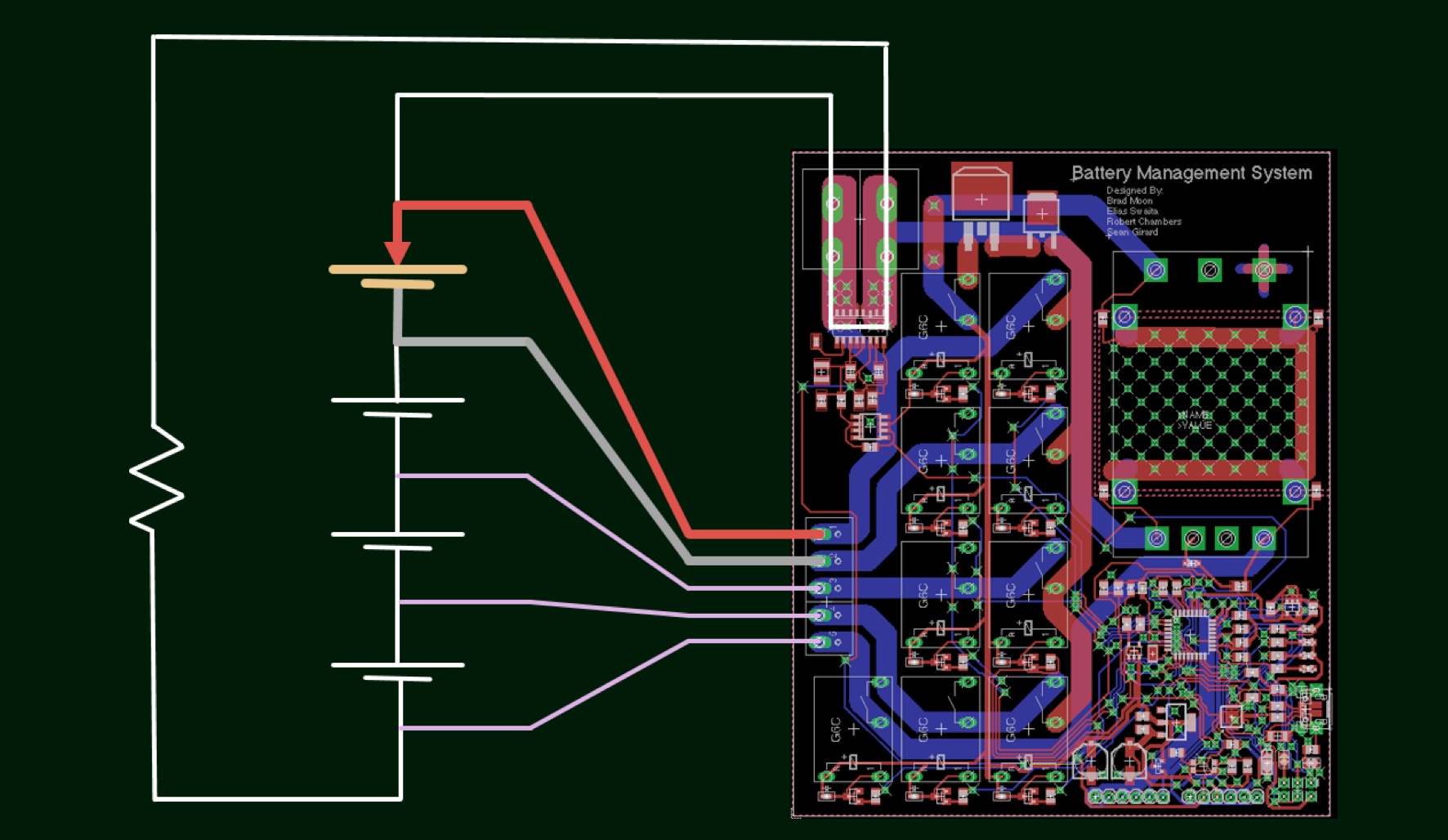
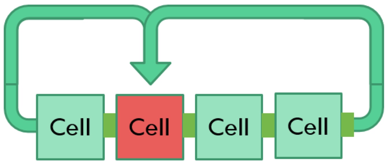 The goal of this system is to prolong the life time of battery packs. Our system transfers energy from the battery pack to any weak cell. The figure to the left shows a pack to cell active battery balancing topology.
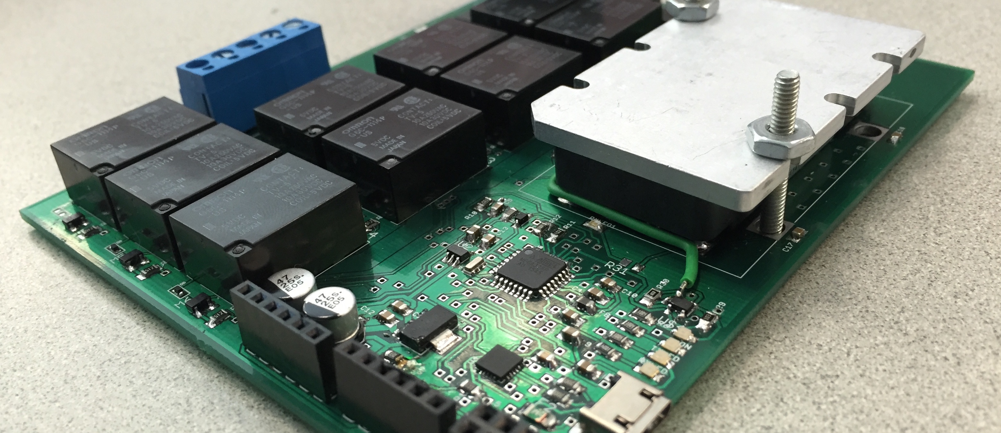
The overall hardware design consists of a step-down DC/DC converter that outputs 5V. The 5V supplies power to the entire board and also charges the weak cell. A Hall effect current sensor, along with an analog to digital converter allows for the system to calculate the state of charge of the current cycle. The function of the microcontroller is to determine which of the cells are degraded and the difference in energy content between the cells. Once the weak cell is detected, the system will begin charging the cell untill the energy content of each cell is equalized.
The three primary functions of the terminal pins are shown in the three figures below. The first image shows the relays connected such that the pin is connected to the +5V of the DC-DC converter. The next images show the terminal pin being connected to ground and the final image shows it being connected to the microcontroller ADC.
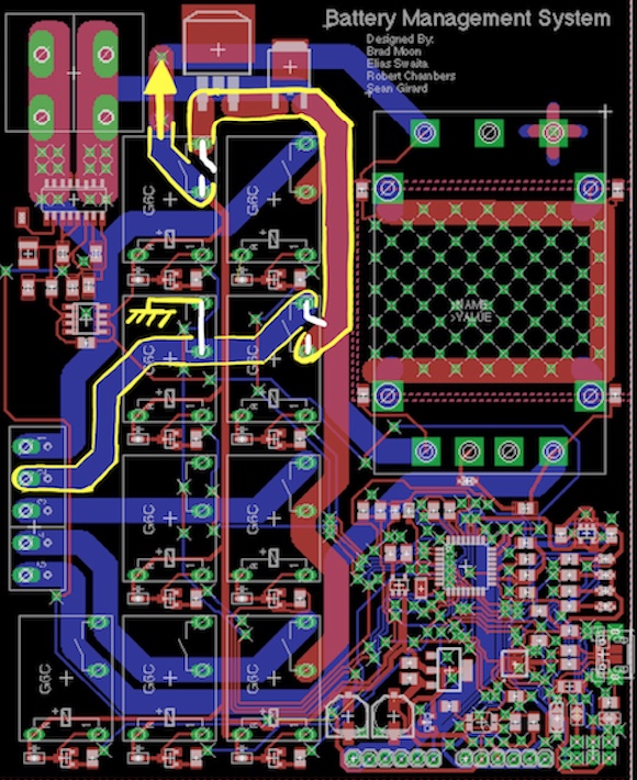
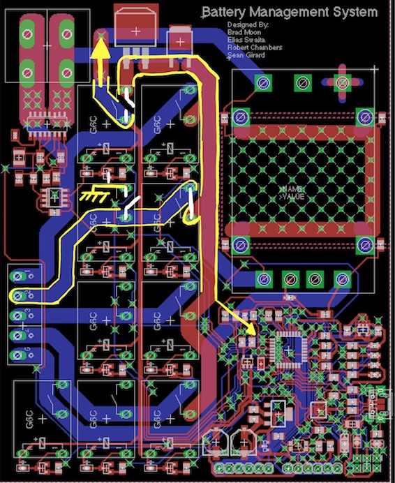
Terminal to 5V
Terminal to Ground
Terminal to ADC
The three images below shows how the battery management system is connected to a load and the three major capabilities of the battery management system. They are as follows: measure current, read cell voltage, and charge cell. Since the hall effect current sensor is connected in series with the battery pack and the load, we are able to determine the amount of current that is delivered to the load. Reading the voltage of a cell is achieved by connecting either side of the cell to the ADC and ground as discussed above. Lastly, charging the cell is achieved by a similar method of connecting either side of the cell to the power and ground, again as discussed above.
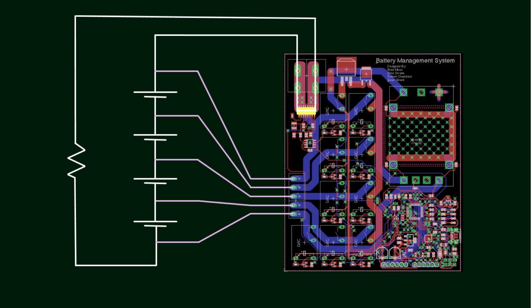
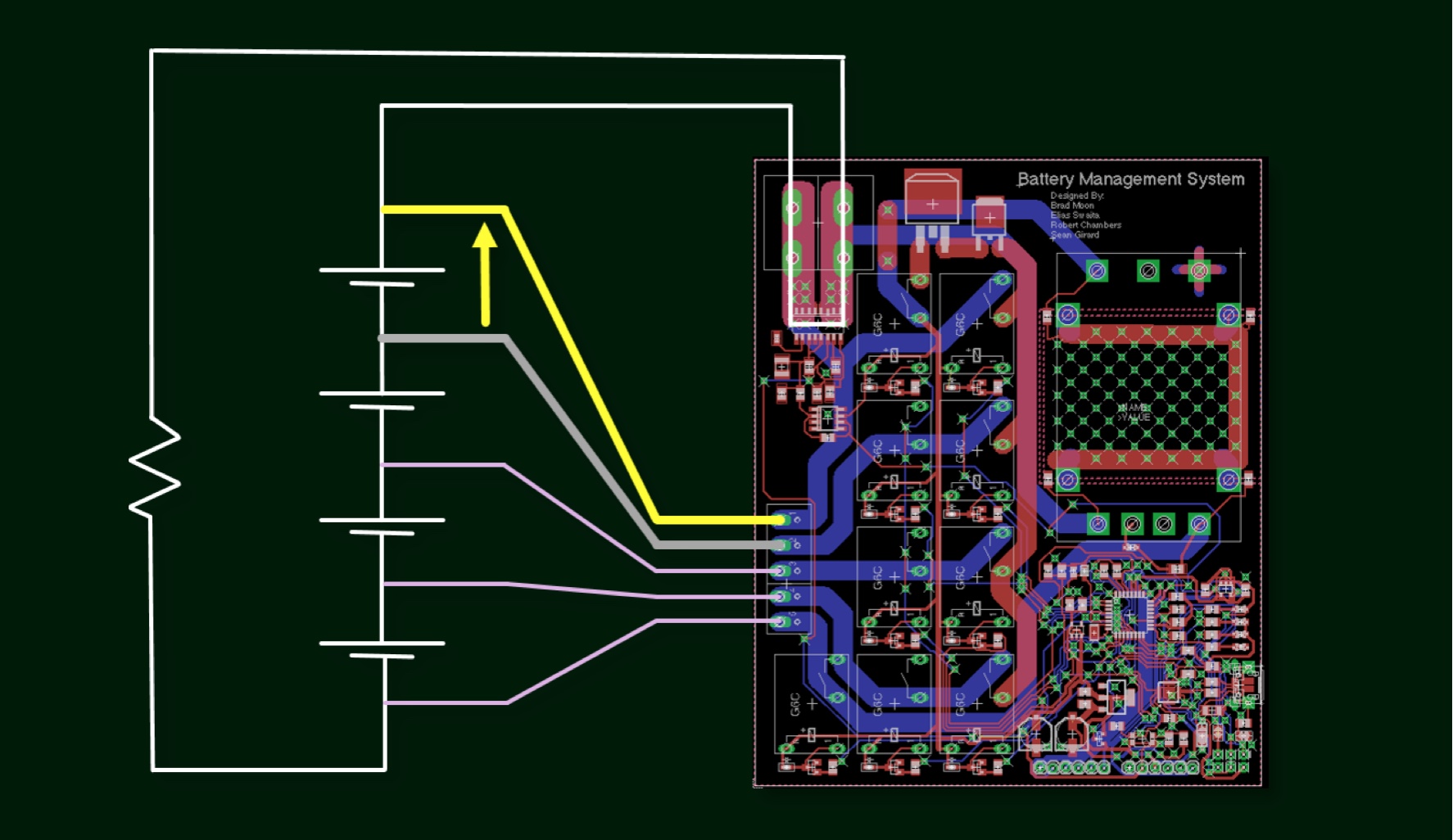
Measure Current
Read Cell Voltage
Charge Weak Cell